Kori Chapic's Senior Thesis e-Portfolio
Construction Management Option
Cleveland Clinic Cancer Center
Cleveland, Ohio
Technical Assignement 1: Project Management
Overall Building Information and Statistics
The Cleveland Clinic Cancer Center located at the corner of East 105th Street and Carnegie Avenue in Cleveland, Ohio is a new construction project priced at roughly $276 million and containing a basement/lower level, 6 floors, and a penthouse. This approximate 377,000 Square Foot construction project is scheduled to complete in early 2017 and service as a Medical Office building for patients, doctors, and nurses alike.
Project Schedule Summary
One of the most time consuming and critical parts of any project could arguably be the planning and preparation. As the Cleveland Clinic Cancer Center proves, after the NTP it took roughly 16 months to begin demolition in preparation for the new building. In those 16 months concept development, designing and design development were at its peak. The design phase was not complete when the demolition and excavation began. Whether it be because of time constraints or impatience, the project was underway.
As the superstructure was being placed and the concrete decks started to be poured the project started to really speed up. The Cancer Center project schedule begins to contain a lot of overlaps. One reason for so much project task overlapping is because of the large scale of this medical office building. Because each individual floor is split into two sections, West and East, when one trade finishes on one half of the building the following trade can move on the same floor.
One very important aspect about the floor MEP systems is the difference in duration for Basement through level 3 compared to the rest of the floors. This is due to the fact that the upper floors are simply office spaces and do not require Medical Gas and Pneumatic tubes. Also looking at the Penthouse the amount of connections, systems, and congestion of the incoming systems this makes sense that there will be excess time spent there. Upon the arrival of the end of the project, commissioning for air and water as well as all complete systems is done to avoid a large time gap between finishes and turnover. The punch list is important to create and complete while the project nears the end so the contractors do not relocate their tools, manpower, and materials back to the site after they have left. The turnover of the building cannot happen without the certificate of occupancy and after that the building can be occupied.
Building Systems Summary
Demolition and local conditions
Before any site work or excavation can begin the
existing buildings on the site need to be
demolished. Because of the age of these buildings
the removal of asbestos and hazardous materials
are a serious health and safety risk that will need
special care removal. The utilities that run beneath
the site currently will all be removed and/or
rerouted due to the large excavation that will
occupy the center of the site over 20 feet deep. On
the current land plot of 5.56 Acres the major soil
composition is urban soil. There is also parking and
other sidewalks within the red boxed existing
conditions on the previous page that will also need
removal before excavation begins. (See image 1 in
appendix for demolition details of existing conditions)
Structural Steel
The Framing on the Cancer center is primarily structural steel with Braced framing strategically placed throughout to withstand horizontal loading. The Structural steel framing is tied in to the slab with composite shear studs at every major beam. These shear studs tie into the reinforced concrete to also give the entire structure more latter bracing for wind and other horizontal loading.
The most interesting structural feature of this building is the large cantilevered section of the south facing side of the building. With approximately a third of the building being cantilevered the structural engineers had to create a unique solution to adequately transfer the loads of the building into the foundation. As you can see in the figure below this was done by creating very large moment connections at the top of the structure with gusset plate connections. These gusset plate connections are located at the top of the structure where the two red highlighted steel pieces come together to make a point.
Cast‐in‐Place Concrete
Another unique aspect of this building structure is the amount of cast in place concrete that will be used. In the lower basement level the Linear accelerators are radioactive machines that need to be contained so they will only effect the person that is receiving treatment. Because of this there are two different methods that could be used to trap the gamma rays. One way would be to completely line the room with lead, or the other is to make the concrete walls so thick so the radiation cannot penetrate completely through them. Because of the cost the better decision was extra thick concrete. As a result, there are walls within the Linear Accelerator section of this building that are near seven foot thick of concrete.
Mechanical System
The Cancer Center will serve as both an office space on the upper floors five and six and also medical infusion rooms and cancer treatment center from floors four and below. This is a primary reason the mechanical system is designed with four air handling units that service a variable air volume system. The entire project contains roughly 400 VAV boxes both supply and return air back to the air handlers located in the penthouse. Due to the excessive loads of the medical portion of the building there will be two custom air handling units placed to handle the lower level through the fourth floor. The other two modular units will be used to service the east fifth and sixth floors and west fifth and sixth floors respectively.
The systems use mainly ductwork which are distributed vertically throughout the building in large vertical shafts indicated on image below. The fire suppression system is a complete fire suppression system and fully covers the entire building.
Electrical System
The electrical system has two main feeder for the building that come in at 15kV a piece. These feeders service switchgear at the lower level in the most north Eastern part of the basement. From there the switchgear distributes the power throughout the building panels. This electrical system contains a large amount of redundancy because of the importance of the medical equipment contained within the building. There is an Uninterrupted Power System, UPS, which is 300kW in order to withstand the electrical loading of the building enough for the backup generators to kick on and start up. These generators are 2000kW and exist in an emergency electrical room on the 7th floor.
Curtain Wall
The envelope of the entire building is a large wrapped curtain wall of glazed glass with about 20‐30% of the building with a stone curtain wall system. There are also aluminum louvers located at the top of the building for the intake and exhaust for the air handling units. Because the building is so high in the air the construction process has been modified to make the curtain wall system installation move faster. The system consists of a smaller more portable floor mounted crane/hoist located on the floor above to drag and hold into place the curtainwall system for the floor below. The only issue with this is that the workers would need full access to the floor below which prohibits others from being able to complete work on those floors during that time. The curtain Wall system is responsible for not permitting condensation due to temperature differences from the outside and inside, must be designed to withstand +/‐ 27.5 PSF of latter loading from wind. The System must be designed to account for 40PSF ground snow load and 28PSF roof snow load plus drift. The safety factor for the system is 1.5 and the entire system will be installed with the Cleveland climate in mind.
Support of Excavation
The excavation depth of the project exceeded 25 feet in many locations so excavation support was very necessary. The support system used was soldier beam and lagging. In the south west corner of the main structure of the building there was a dewatering system that was connected as soon as the contractors began to dig below the water table. This system works well but is just temporary until the complete plumbing and drainage is completed and hooked up within the building.
Site Logistics Plan
It is important to note that the site logistics plan provided is for all the phases of steel erection. The superstructure of the building is divided into four separate sections being the NorthWest‐1, Northeast‐2, southwest‐3, and Southeast‐4. Because of the large scale of the project the different crane locations are there to show the different locations and crane placement during that phase of steel erection. As shown there is a lot of room to travel around the West, north, and east ends of the building. The South end will be more available when the ceiling on the basement linear accelerators is completed and backfilled. The major concern in this schematic is the crane locations and how the placement is mostly right in the traveling paths of people, vehicles, and/or machines. This site logistic will help all those working on site to see the danger and avoid those areas during that phase of construction.
Project Cost Evaluation
In conducting the square foot estimate there were many inaccuracies and differences from what was stated in RS Means 2014 and what the Cancer Center actually contained. One of the biggest differences was the inclusion of the Linear Accelerator Machines that will be going into the basement of the new building. Each of these machines alone cost at least $10 Million so I decided to get a better measurement and added that as an additional cost. With the scale and casework going into this building there was also a near $4 million addition for casework and other security and communication devices that would be necessary for infusion rooms. Having this project in Cleveland had a cost code location multiplier of 1 so that did not change anything.
One of the largest cost impacts was the HVAC system at 21.4%. This comes to no surprise especially after getting to understand that there is not only supply duct but also return duct in medical and health facilities. What seems surprising is the cost of the enclosure only at 6.9%. Assuming this may be a reason why glass façade was not on the list of building enclosures this percentage makes more sense. This estimate for the square footage was approximately 14.49% lower than the actual listed cost. For detailed cost breakdown and cost multipliers for the square foot estimate that can be found in the appendix.
Client Information
The Cleveland Clinic is known worldwide for their excellent healthcare services and treatment centers. The Clinic Began in 1921 and today serves as a, “Nonprofit, multispecialty, Academic, Medical Center”. The current Cleveland Clinic Taussig Cancer Institute serves many different cancer patients and prides themselves on world class care. The Cleveland Clinic is known for innovation, continuous collaboration, extensive research, and always looking for another reason to give people with cancer hope. With Many Philanthropic donors and the Clinical Campaign that has raised near $600 million the clinic will continue to look to innovate and strive to be the best in healthcare. As the architect, William Rawn Associates is known for their world class building designs but they have never designed a healthcare facility. The clinic hopes the new perspective brought into the healthcare industry will provide a different than mainstream approach to innovation.
Project Delivery System
The Clinic’s role on this particular job is different in that it is said to be an OCTPD which stands for Owner Controlled Team Project Delivery. In this delivery the Cleveland Clinic and its owner representatives are in charge of many of the GMP contracts between them and the Prime contractors. It is interesting because Turner Construction is serving as the CM on this project but have been said to be serving almost as a GC. In any case the main purpose of this project is LEAN design and looking to find better and more innovative ways to collaborate throughout the project progress. The MEP design by BR+A is one of the largest costs to the project and is another reason there are many different players involved with this side of the work. BR+A hired a representative as a Subcontractor in Karpinski Engineering to handle day to day fielded questions. With that Relmec Mechanical is fabricating and placing the plumbing, steam, medical gas, sheet metal, waste and vent, and domestic water throughout the building while Southland Industries is assisting with the BIM design process in a joint venture contract. Altogether communication flows are supposed to be fluid and continuous.
Staffing Plan
As a CM Turner had a great deal of employees able to handle the wide variety of companies, disciplines, and still stay on task with the overall project schedule and daily tasks. The main job Turner takes charge of are keeping the project moving along the schedule path and hitting key dates. Turner has a project manager and/or engineer that is in charge of each of the different systems and makes sure the proper submittals, orders, and deliverables are all on schedule and initiates meetings for any issues that need to be resolved.


Technical Assignemnt 2: Production Analysis
Executive Summary
The Cleveland Clinic Cancer Center contains an interesting and intricate subgrade that required some extensive engineering and planning before any groundbreaking began. This report summarizes the schedule, cost, and logistical challenges of the Cleveland Clinic Cancer Center’s dewatering system, excavation, Support of excavation system, and foundation system.
The production plan of the subgrade steps were very influenced by the existing site conditions. The high water table required and extensively preplanned dewatering well system. The sandy soil was found to be a large influence to the schedule and equipment of the excavation and helped these processes move a little more smoothly. Although the sandy soil made excavation easier, the excavation needed soldier beam and lagging implemented to prevent the collapse of the excavation walls and provide safety for all the workers in the excavated hole. This intricate process required additional time and provided additional challenges to the excavation process.
The cost of these activities were found to be $22,482,740.00 even excluding the dewatering system process. It was discovered that this cost did not match well with the square foot estimated cost of the project which was calculated at 1.7% of the total building square foot estimate cost which worked out to $2,148,877.10. The dramatic differences were found to be a result of the enlarged basement footprint, extreme depth, extra hydraulic slab considerations and foundation redundancy for the structure above.
The site logistics were another battle that needed much planning before the excavation process began. With the large excavation hole being dug in the middle of the site mobility of site cranes, trucks, excavators, and other equipment was limited to the perimeter of the excavation. The south area of the building was no longer able to be traversed by trucks or machines because it was too narrow between the excavation and the site fence. Also the tunnel excavation eliminated round-about traversing in the north western corner of the building.
The system process and intricacies were experienced by the onsite staff and managers coordinating the process and recording the daily progress and production. As a student learning the process of the dewatering and support of excavation was a completely new topic. As explained by Turner’s Project manager the challenges of the site soil condition and the high water table were the cause of these major systems implementation.
In an additional interview with the site foundation subcontractor’s project manager the concrete placement and process and placement of the mud mat, waterproofing, reinforcing, production slab and hydraulic slab became much clearer. Labor tracking and production made sense when looking at these stages.
System Construction Means and Methods
The Process
The Cleveland Clinic Cancer Center foundation is a completely engineered concrete system that required much work before the concrete could even begin to be poured. The location of the water table in this area of Cleveland is actually just under fifteen feet of surface soil which means an engineered de-watering system needed to be implemented. This system consisted of thirty-one wells that surrounded the perimeter of the building footprint that penetrated 30 to 35 feet deep with a perforated pipe in each well. The wells were connected with a header pipe and routed to two main discharge stations at the southeast and southwest corners of the building footprint as indicated on the site logistics plan in the appendix. These discharge stations were connected to the storm water system and thousands of gallons of groundwater were directed off site daily. As this process was continuing, the excavation followed closely behind. The excavation was conducted by track hoes from west to east starting in the tunnel then moving chronologically through the different excavation areas as indicated by the numbers 1-4 on the Logistics plan in the appendix. As the water table dropped the excavation was able to proceed.
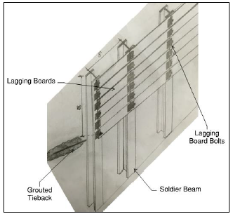
While the excavation was continuing, the soldier beam and lagging needed to be placed in order to ensure the workers safety and prevent the collapse of excavation walls within the soon to be dug 30’ deep hole. The Ibeams for the soldier beam and lagging support of excavation system were drilled in every other manor, similar to the wells, around the perimeter of the building but much more frequent (roughly every 8’). A crane was used to drop the beams into the hole and then the beams were grouted at the base. As the excavation continued the lagging boards needed to be placed every time the depth reached 5’ to maintain safety and ensure no collapse. At a depth of 10’ and 25’ there were tiebacks that were shot back and grouted into the soil to provide adequate tension on the beams of the support system and prevent collapse. This special tieback machine is an intricate piece of equipment that is specifically designed to minimize the moment force at the base of the grouted Ibeams.
(See the image below for a detail of how this system is designed).
Image 1: Image of a detailed example of the soldier-beam and lagging support of excavation used for the entire perimeter of the Cleveland Clinic Cancer Center’s basement footprint.
Once the excavation reached the proper depth a rough, 3” concrete mud-mat was pumped and placed on the base so that there was a better surface for the construction to continue instead of wet, muddy soil. After the mud-mat, the drainage and waterproofing was placed and covered with another 3” concrete slab. This slab over the waterproofing was placed as a protective layer, again, for the workers to place rebar, run materials and machines, and walk about the base of the excavation without damaging or disturbing the already placed work. The most significant and important structural layer was the hydraulic slab that ranged from 3’-4’ in thickness throughout the entire excavation. This slabs thickness was necessary because of the high water table and to prevent hydraulic lift when the dewatering system would shut off after the foundation system was completed. The foundation walls were 2’ thick concrete cast in place with rebar cage reinforcement. The formwork was placed ahead of the reinforcing crew which was then followed by the concrete crew. The reinforcement was created horizontally on the concrete hydraulic slab then lifted by the 60 ton all terrain rubber tire cranes up and into the formwork and lowered into the foundation formwork. Again, concrete placement was by pump then vibrated into the foundation wall formwork. Once the forms could be removed some light touchup work was done to make sure the wall was smooth and the foundation was complete.
Performance and Quality
The project has a third party inspector Solar Testing. Solar’s job was to inspect the subgrade and make sure the proper depth was reached and was on adequate shale to support the structure. All concrete pours had slump and cylinder tests to ensure the proper workability and compressive strengths were met. Before any mix design was brought to the site they all went through the submittal process and needed to be reviewed and approved. Special steps were taken for seemingly simple project activities such as backfilling behind the foundation wall. This needed to be done in lifts because proper compaction needed to occur in order to prevent uneven leveling and/or settling. Having a third party inspector on the job allowed for more frequent constructability reviewing and continuous consistency throughout this crucial engineered system of the building.
Production Schedule
The production schedule for the dewatering, excavation, support of excavation, and foundation portion of this project, which you can find in the appendix, falls towards the beginning of the project overall schedule as you can see from the overall schedule in Tech 1.
These engineered systems are started and completed in just about seven and a half months. As you can see from the overall project schedule, the dewatering/excavation of this project cannot fully begin until the demolition of the existing buildings, parking lots, sidewalks, and storm drainage are removed from the site. This portion of the project is also on the critical path and needs to be completed before the steel structure will begin to be erected.
Within this production you will notice the importance of the major milestones in order to move forward with the foundation system. A typical trend that could be identified is the completion of excavation within a given area prior to the mud mat being poured. The major floor pours of the mud mat, production mat, and hydraulic slab are all completed in one single day and cannot be done until the predecessor pour is completed and cured to a certain degree.
Site Plans and Logistics
The site logistics throughout the dewatering, excavation, support of excavation, and foundation of this building had to be well planned and utilized because of the lack of site space available. In the beginning the site had much space because there was not a 30’ deep hole the size of the basement impeding site movement. The dewatering needed the drill and crane movement about the site foundation perimeter before any of the excavation began. The dewatering system began on the south side of the tunnel and circled around the building perimeter in a counterclockwise direction (see image 2 below for clarification). The crane also followed the path of the well placements.
Image 2: Image of a detailed example of the work-flow of the dewatering installment. (Drawing borrowed from the Cleveland Clinic Cancer Project Team)
Because the tunnel needed to connect to the existing Crile Building the excavation began there in order to match up with the floor elevation in the existing building. This created a barrier and inability to circulate the site which only allowed the two gates to be used on the east site fence as means of a looped entry and exit (shown by the black and yellow striped path on image 3). As the excavation continued the soldier beam and lagging followed on either side of the excavation. Where the tunnel met the large excavated basement there were 2 crews working on the excavation support one heading south on the western most wall and one heading east on the northern wall (See Image 3 below for clarification).
As mentioned earlier, this process of excavation, support, and foundation generally moved west to east. The numbered divisions of area show roughly where excavation was deemed to be okay and at proper depth the mud-mat was poured to help with the workability and cleanliness of the site conditions. As the excavation moved east and neared the edge of the basement perimeter the truck
Image 3: Image of a detailed example of the work-flow of the soldier pile and lagging installment. (Drawing borrowed from the Cleveland Clinic Cancer Project Team) ramp was removed and the excavation needed to be excavated as the truck entrance and exit path grew smaller and smaller.
The numbered areas represent the workflow for the waterproofing, protective slab, rebar cage, and hydraulic slab. As soon as one area was completed by a previous trade it was released to the next trade to begin their work. The foundation walls followed the same path as the support of excavation by splitting into two crews at the tunnel entrance. This allowed the hydraulic slabs to be poured first then, while the slab crew moved to the next area, the foundation wall crew was able to start creating the rebar cages and placing the formwork on the poured slab area.
Production Analysis
After in depth discussion with the project manager on site and after looking at the crew sizes, duration, and scope of work that was done in the given timeframe, the production was very efficient. The overlap and turnover of different areas within the excavation allowed for trades to work together and combine time and activities of the project which allowed for the schedule to be compressed overall. The cranes’ use throughout the project was efficient because the time was not wasted by an operator waiting to make lifts nor overloaded and backed up with too much material to handle. Both cranes had individual crews working directly with them and were able to keep the workflow moving smoothly. The concrete pumps were a huge time and manpower efficient method of placing concrete. Needing only 3 workers to cast-in-place a 60’ foot wide by 25’ wall not only saved on much manpower that other methods of placement would require. Not only was this process quick but it was also easy to transport and reach deep into the center of the excavation down 25’.
As the excavation of the tunnel eliminated round-about traffic flow within the site the method of starting at the furthest point within the site at the tunnel and working out from to the east of the site provided a nice workflow and didn’t create crossing or interference of other trades work. The rerouting of onsite trucks for excavation removal and concrete pouring was also efficient because trucks did not have to enter and exit through the same site gate. When trucks have to maneuver on a jobsite in order to turn around this causes unpredictable time and efficiency delays. By having a single path and movement of site traffic much of the time delays were avoided entirely.
The support of excavation was another efficient choice because it could be done congruently with the excavation and didn’t prevent workflow. The only issue with this method of excavation support was the points within the system at which piles needed to be drilled and grouted. This activity took a little bit more time but what was more inconvenient was the pile machine that needed to be in the hole and then moved when the excavation needed to be dug lower. This machine needed to be fed with grout also so it was not a simple, handheld tool (See image below).
Cost Analysis
The cost estimate for the dewatering was not included in the cost estimate provided in the appendix. The cost estimate provided is attempting to capture the foundation, support of excavation, and excavation costs of the Cleveland Clinic Cancer Center. Comparing this cost to the square foot estimate does not come close to the substructure percentage provided from the original building cost breakdown previously produced. Because this building has a much larger basement footprint perhaps the percentage breakdown from the overall building cost did not include this.
This building has 3 layers of slab on grade concrete that are very unique. The mud mat and production slab are both relatively thin layers, only 3-4”, which is not the dramatic cost difference. The gravel fill in the basement ranges 3-4’ thick at some points within the basement slab system. This in addition to the 4’ thick hydraulic slab with rebar cage containing #8 and #9 reinforcement is not the typical floor slab that is usually put into basement floor systems. Because of this the RS Means square foot typical estimate doesn’t really align well with the more detailed equipment, material, and labor loaded cost estimate provided in the appendix.
Another key component that was attempted to be captured was the support of excavation with the soldier beam and lagging. Because there was no assembly for this in order to try and capture this cost finding the H-sections that were used as piles was as close as could be reached.
Image 4: An example of the size of the tieback machine used for the grout supported tiebacks which were used at each pile for the soldier-beam
and lagging system. (Image borrowed from: http://www.coluccio.com/services/drilling/tie-backs/)
Equipment that was used was captured in the assemblies estimate including the cranes in the reinforcement lifting 1.5 tons of reinforcement daily per crane. Also the excavation needing to be hauled off site was considered also in the assemblies estimate. The excavating machines that were used also were captured in the assemblies of the excavation process. Because the soil was mainly san there was no need to include any hydraulic machine jackhammers because the shale didn’t exist until 30’ deep.
The cost estimate is very unique for this substructure and general quantity takeoffs and assemblies can only capture a portion of the intricacies of this system. The best form of estimate would be to have prior project information and look at historical data.
Logistical Analysis
One of the difficult problems with this site is the lack of space at the south end of the site. This section is actually not protruded above the surface but is solely part of the footprint of the basement. That being said when the project is complete this will actually be the most spacious part of the site but because the excavation hole is open to above during construction it prevents use of this area of the construction. One of the possible options that could have been addressed would be finding some sort of method to open a large enough path so vehicles and equipment could fit through the space between the excavation and the site fence. By opening this pathway there is a better chance the south vehicular gat could be used to mitigate traffic problems on site and through Carnegie Ave. and E. 105th. The temporary de-watering system was completely necessary but the location of the discharge locations could have been better placed. Maybe, because the south side of the building excavation really didn’t have any worker or vehicular traffic flow these stations could have been set up there. This would have allowed for the opening of the current locations and also wouldn’t change the availability of the space that is not being used anyways.
Having the overlap of the support-of-excavation system could have been replace with something like a slurry wall or shotcrete. Because of the nature of the sandy soil the idea of a slurry wall was not as favorable as the soldier beam and lagging. The same issue comes to fruition with the shotcrete wall support. Although another viable option the size of the excavation wall is so large that the amount of concrete needed to cover, the amount of tiebacks needed for the sandy soil, and the time constraints would not make for a better support system.
Having the concrete pump stationed on site could have caused some more congested during concrete pour days. However the alternative method of crane and bucket would require so much more manpower and require so much more time that partial congestion was the better option.
Schedule Acceleration Scenarios
The foundation completion is a critical milestone in order for the rest of the structure of the building to go up the time it takes to complete the foundation will directly affect the overall project schedule. As previously mentioned there were different methods of support of excavation and concrete placement that were considered for this project. Starting with the support of excavation the option that was suggested was the slurry wall option. Some of the decisions that reverted away from this option was the fact that the support walls needed to go 30-35 feet deep at most points. The amount of slurry that would be needed to properly implicate this system would be very large in order to provide the proper hydraulic pressure the cavity would need to not collapse. The slurry wall would then be pumped with concrete at the base and the slurry would be sucked off the top by another machine, cleaned and ready for reuse. The cost of the concrete would be much larger for the slurry wall because the thickness of the wall would need to be adjusted for the large depth. With all of the factors considered this option did not make sense with the site logistics and project duration and critical path.
The concrete placement method was originally thought to be done by crane and bucket because to rent a concrete pump truck for the day is approximately $2,500. After further analysis of the job requirements with crane and bucket method of placement a couple of counter arguments can be mad to make the $2,500 initial cost ignorable. The manpower to place the concrete with crane and bucket is the crane time with operator costs and occupying the crane which enables the crane from doing other work, it requires a crew of 4 or more guys to help hook it up, fill it, then dump it, vibrate it, and finish it. Not to mention the additional safety hazard when flying a steel bucket full of concrete above the jobsite as well. Needless to say this option would have actually slowed the project down.
One option that could have been explored were the construction of the reinforcement cages. This operation was done pretty efficiently by assembling them horizontally then tilting them up with cranes and putting them into place. A potential schedule acceleration could have been to prefabricate these rebar cages offsite and had them shipped and unloaded directly into the forms. This may have sped up the foundation wall process and also allowed to free up some space in the excavation hole for other trades. The negative implication would be that a warehouse would probably need to be rented to do this work offsite and provide enough room to complete.
Constructability and Logistical Challenges
One constructability challenge of the soldier-beam and lagging system were the tiebacks at a depth of 10 feet and 25 feet at each soldier beam. The soil was more of a sand material which provided some constraint to the strength of the tension that could be reached by the tiebacks to pull the system and support the undisturbed soil. As you can see in the drawing below the tiebacks were grouted back into the undisturbed soil to prevent the wall from falling or caving in where the excavation area was. A specific tension needed to be reached at each soldier pile to ensure there was no weak point throughout the entire system. Sometimes when the grout was being pumped into the soil voids in the soil would be hit which would inhibit the grout from reaching proper strength.
To amend this they would try to see if adding slightly more grout to see if the void would be filled. If this failed the last resort would be to add a steal beam that would stretch the length of 3 soldier beams. This beam would be able to transfer the tension from the piles adjacent to the failing tieback and provide the appropriate support the center tieback was missing. Fortunately this was not as common as it could have been and there were only some adjustments that were made throughout the entire soldier-beam and lagging system.
Image 5: A detail of the Soldier Beam and Lagging system used to support the Cleveland Clinic Cancer Center foundation and basement excavation.


Technical Assignment 3: Exploring Problem Challenges and Opportunities
EXECUTIVE SUMMARY
The contents of this technical report include a detailed interview with the Cleveland Clinic’s Project Executive and some key takeaways from that discussion. The details that were covered within the interview included project challenges such as the constraints of project shutdown notices and planning. The Cleveland Clinic’s high requirements for quality and other intricate requirements that the clinic has experienced problems with in the past requires constant quality control checks and above minimal standards of the Cleveland Building code.
Value engineering implementations such as location differences that allow for redundant seismic considerations to be eliminated are large cost savings on this project. Also, after further analysis and discussion, determining that the custom air handling units could be reduced in size was another huge value engineering implementation. Although value engineering may save money, it does not always meet the owner or architects needs for the building design as we discovered with the exterior stone façade.
Looking deeper into the industry issues the PACE roundtable addressed some significant industry issues concerning decision making and collaboration into the field. The issues suggested a deeper understanding of teams and better emotional intelligence between team members within collaborating teams. This collaborating issue between two teams is usually an initial sign of a failure, or many challenges and issues throughout the project duration. These ideas then triggered other feedback from industry leaders.
The feedback received included an emphasis of Lean concepts and labor tracking within the subcontractors and throughout the construction duration. Not only will it assist the project management team of project process durations but it will also provide great review material to be later visited for future estimating. Other feedback included transparency of information sharing but realizing that this is not the same for all members on the project. The generation gap needs to be addressed with the transferring of information and not mitigated by simply implementing “Blast” emails.
With the BIM execution plan it was discovered that the current BIM use on the project aligned closely with what was thought to assist the project. The balance of level of detail with time and cost ultimately equated to the plan proposed and evaluated.
LEED on this project is projected to achieve a Silver rating, even though through my analysis I determined LEED Gold was very possible. WIth the possibility of LEED Gold able to be achieved, the realization of the project being a medical/office building did not seem as achievable in reality as it did on paper. The Cance Center needs redundancy and special considerations for special medical equipment.This Facility also needs specific power requirements. The Silver rating was determined to be the best fit for LEED initiatives and also meeting the Cleveland Clinic’s requirement of quality and cost.
PROJECT EXECUTIVE INTERVIEW
PROJECT MANAGEMENT SERVICES
The Cleveland Clinic project is unique in its delivery method. Owner Controlled Team Project Delivery (OCTPD) is not very common in the construction industry for ways of contracting and delivering a project but is the unique and chosen method for this project. The major difference between this delivery method and that of an IPD project is the contracts for the subcontractors are held with the owner directly and not held entirely with the whole project team. Turner Construction is in charge of assisting the construction management of the entire Clinic project. As part of their construction management services they created, control, and maintain the overall project schedule, they also provide the services for releasing and managing the bids for the subcontracted work. Turner does not always make the final decisions when issues arise but they are the main contact to the Cleveland Clinic for big financial, or scope changes or challenges.
As a medical office building construction project the majority of the challenges arise on the medical portion of constructing. Throughout the project construction the surrounding buildings are to be fully open and functional. This includes not only the elements within the building such as medical gas, electricity, and water but also outside of the building such as deliveries, pedestrian traffic, and emergency vehicles such as ambulance access and/or fire department access. With this being a constraint to the client and the project team the phasing of this project needed to be well planned in advance and any necessary shutdowns need to be reported at least seven days in advance to the Clinic. Also if there are any shutdowns such as medical gas the Clinic needed even more warning so they had adequate time to transfer patients or be able to provide portable medical gas until the gas could be turned back on. This provides a challenge to the project team because they need to keep on track with the schedule if they are planning to coordinate with an active medical facility.
The minimal code requirements within the municipality of Cleveland are less than some of the Clinic’s standards. The Clinic requires some redundancy and higher quality products because of prior incidences and to minimize maintenance time and costs later in the building life cycle. An example of this is that steam pipe needing to be schedule-40 in Cleveland but the Clinic requires a higher schedule- 80 on their new construction projects. This is a cost constraint because the higher schedule-80 pipe costs more and there is no way to avoid this material cost. Some of the steps taken to minimize the field work on this pipe were prefabrication. Doing welds and connections in controlled environments minimizes field work and allows for better quality. Similar situations with other MEP system elements were occurred through the building which all required planning and adequate cost analysis before being implemented.
The Cleveland Clinic is continuously operational so one consideration for the work being done near the adjacent Crile Building loading dock was to have this work being done on off hours. This would not interfere with the Clinic’s operations during the day and also would not need any shutdown notice to be planned and submitted. As simple as this sounds there are some significant cost implications that has potential to not fit the Clinic’s goals with this decision. Although the dock would be completely operational throughout working hours, labor costs are higher for off hours and would cost the task more to be completed in different hours. Not to mention if they needed lights and other equipment to be able to see the work space which also ties into safety. Altogether the Clinic was able to compromise with a shutdown notice to mitigate these other project impacts of cost and safety.
VALUE ENGINEERING TOPICS
With such a large scale project there were many opportunities to use value engineering. One of these instances was in the design from Stantec in San Francisco, California. In California there are considerable seismic constraints that need to be taken into account which do not apply in Cleveland, Ohio. One of the large value engineering strategies that was assessed on this project was identifying the unnecessary seismic elements that Stantec San Francisco designed and eliminating them from the material and labor costs. This included the four inch metal studs in the walls. Although this seems small, the building contains a lot of interior walls and a small adjustment such as this is a repeatable item that saves the project considerable dollars.
Another considerable value engineering strategy was that of the mechanical air handling units. Originally the design consisted of four custom air handling units to supply the basement through the 6 th floor. As the design team reviewed the drawings they realized the 5th and 6th floors were typical office spaces that did not need to meet special mechanical supply or return air requirements. After some discussion the project team realized this was to accommodate any changes that may occur later on these floors such as transforming these spaces into patient rooms. With further research the Clinic realized that this did not align with how they prefer to occupy the different buildings and they would never remove doctor’s offices entirely from one building to create a complete patient building. This realization allowed for a reduction of CFM for the 5th and 6th floors and therefore allowed for a reduction in the air handler unit sizing. Instead of four custom units the project team was able to reduce the units to two custom units and two modular units. This saved the project considerable dollars without compromising the goals of the Cleveland Clinic.
One area that was explored for value engineering was the stone on the exterior façade of the building. The stone that is to be used is natural stone that is also a natural color. Due to the nature of natural stone there tends to be different and wider range of color variations from different slabs that are extracted from the earth. The architects were concerned with this different color variation in that it 5 would give the building aesthetics a checkerboard look. Although it would cost the project a little more money, the architect and the Clinic agreed to pay a little more money upfront in order to ensure the consistency of colors for the exterior façade would be met.
CRITICAL INDUSTRY ISSUES-PACE
At the PACE Roundtable discussion I attended the “Distributed Leadership vs. Centralized Decisions” and “Driving Collaboration into the Field” breakout sessions. Staring with the first discussion of distribution of leadership I was surprised at the seemingly overwhelming preference of distributed leadership. As the discussion continued throughout the breakout session it seemed as if most industry leaders preferred to work with other companies to come to collaborative decisions. With the emphasis on collaboration words such as trust, risk, accountability, responsibility, and behavior came to fruition. This was even more surprising because the conversation transformed from decision making to emotional intelligence and how teamwork could either flourish or perish with the attitudes of individuals and companies.
The second breakout session about driving collaboration into the field also discussed this idea of behavior and how working with the right people is half of the battle. Many of the industry members agreed that a large portion of the project cost is directly related to this topic of fieldwork collaboration. The discussion lead to the idea of the office personnel vs the field personnel, which is the mentality that everyone agreed cannot exist in order to have successful coordination transition to collaboration. The domino effect of being a team player can start at any level and transfer up and/or down the ladder which is why this conversation emphasized the importance of encouraging and seeking advice and input from foreman and engineers to enhance look ahead schedules and daily huddles. With the advancement of technologies there are many helpful information sharing tools such as Bluebeam, Onehub, and Autodesk but some of the challenges arise with generation gaps in using these resources. In conclusion it is determined that the field and office collaboration could improve and diving into individuals and methods of delivery could really aid the flow and cost of a project.
PACE ROUNDTABLE FEEDBACK
One of the large implementations on the Cleveland Clinic Project is Lean concepts and ideas. Running parallel with LEED, Lean concepts are designed to eliminate waste and aid in delivering smooth, ontime, and under budget projects. One topic that was discussed in detail was the idea of labor tracking. Because Lean focuses on how to improve processes and eliminate waste the best way to do this is to know what was previously done and some of the challenges and/or constraints that occur and throw the project off schedule. With better, more accurate, and more detailed labor tracking issues with cost estimates, scheduling, planning, and manpower loads can be better predicted and determined. 6 Another topic that was discussed was the communication within projects. The concept of “Blast” emailing came up because this is the step that has been taken to increase project transparency. One of the issues is that people within the industry have become numb to emails and tent to avoid and overlook emails because they are receiving nearly 100 emails daily! This could be coupled with generation gap of information sharing. Emails may be a sufficient way to transfer information between people aging from 20 to 40 but when there are people who are 40-60 years old working and/or even younger people who are not as familiar with these technologies the information is never received. The overarching issue is that information transparency comes in all shapes and sizes and forms and this topic needs to be addressed by project teams in order to adequately collaborate and communicate throughout the construction phase of the project.
BIM USE EVALUATION
Looking through the BIM execution planning and analysis I found it most useful to use BIM on this project primarily for design reviews, 3D coordination, and compiling a record model at the end of the project. The main reason 3D coordination was primarily chosen is because the level of detail needed to receive this information is appropriate and would most benefit the overall project goals, schedule, and budget. Programming is not completely necessary but it is a simple application that could be applied to the architectural model. This part of the BIM planning provides the owner with a better visual of the spaces within the building and is a great tool for the architect to use to display their ideas. Moving forward the architect would be able to begin a general schematic design and create other templates for the different design engineers to adapt. The Engineers would be able to begin to implement their systems in 3D space and begin to visualize how their system could best fit the program of the building. Once the Engineers have begun their designing the architect can bring the models all together to determine the clashes and create project team discussion to resolve issues before they reach construction documents. At this stage the Owner will also be able to join for a design review of any issue that were unable to be resolved within the project team. Upon agreement and clearing of collisions and discrepancies, the architect could issue construction documents out to the project team. Engineers can use this model to create any prefabrication spool sheets to hand off to the fabrication shop and the architect can continue to develop the prototype that will be handed back to the owner and facilities manager. Upon completing the virtual prototype, it will be the project management staff’s job to finish the compilation of necessary documents and handing off a clean, easy to navigate BIM model that is most consistent with the life-size completed building.
This process aligns pretty closely with the plan on the Cleveland Clinic Project. The 3D coordination was the biggest takeaway from this process because of the implementation of clash detection between different trades. When the electrical conduit clashed with duct in weekly meetings with the electrical contractor, MEP contractor, and fir proofing contractor any existing clashes would be discusses and resolved by the next meeting. This really aided in the transferring from the design model into the 7 construction field because spool sheets were able to be created for plumbing and mechanical pipe as well as FP pipe. With prefabrication efforts the fieldwork was minimized and quality of welds were increased because of the better working conditions of prefabrication.
The project completion model turnover is currently being discussed with the project team and facilities management group to see the best approach and deliverable that the project team could hand over. Having a model is a great tool but if there is little to no use to the facilities management team then the prototype serves no purpose. The team is in discussion currently to determine the most appropriate way to present the project information to the facilities management group to simplify their search for information throughout the building lifecycle.
SUSTAINABILITY IMPLEMENTATION
Through the critical LEED assessment I believe the Cleveland Clinic Cancer Center Project could achieve LEED Gold Certification with 67 points. Major areas where this project achieves a LEED Gold Certification is the location in downtown Cleveland near local transportation and urban environment. You can find the most up-to-date LEED scorecard of my assessment of this project in the appendix. All of the below LEED point requirement descriptions can be found in detail at: http://www.usgbc.org/sites/default/files/LEED%20v4%20BDC_10.01.15_current_0.pdf LOCATION AND
TRANSPORTATION (16 POINTS)
The purpose of these LEED credits is to ensure the site being used is appropriate for access, closeness of amenities, and encourages human health by keeping the location close for pedestrian travel. One of the biggest point retrievals in this category is the Access to Quality Transit. This category is intended to reduce individual person transit. The Project being located in downtown Cleveland is able to take advantage of the bus system in Cleveland so these points are easily attainable.
SUSTAINABLE SITES (10 POINTS)
This Category is intended to reduce as much pollution as possible from construction activities. One of the major considerations for this category include rainwater management. In construction there is a large chance that runoff from the site could cause an issue. On the Cancer Center site they specifically implemented a dewatering system throughout excavation and foundation work to minimize this from happening. These dewatering systems were tied into the existing storm water systems of the city.
WATER EFFICIENCY (11 POINTS)
This category is implemented to reduce the use of outdoor water. The two biggest contributors to this outdoor water consumption include the cooling tower and the indoor water usage. The project’s intent is to minimize the water use by the patients and doctors but that is not always controllable because of 8 the needs of a medical facility. Because of this the cooling tower will use minimal water to cool itself during the summer months.
ENERGY AND ATMOSPHERE (33 POINTS)
The purpose of this credit is to assist in the energy, water, indoor environment, and durability of projects while meeting the owner’s needs for these categories. The largest subcategory for this is Optimizing Energy Performance. Altogether this subcategory focuses on solutions and viable options that could be used to reduce harms and excessive energy use. The Clinic has some specific requirements for energy that need to be met but can most definitely use sustainable energy solutions for a majority of the building operation period.
MATERIALS AND RESOURCES (13 POINTS)
This category is more focused on the materials disposed of within the building and used throughout the building and having the most durability and longevity to reduce environmental impacts of waste and/or poor product quality. The Building life cycle impact reduction is the most prevalent subcategory because its intent is to reuse and optimize performance of materials. We can see this with the natural use of the stone and exterior glazing because these materials are high quality and will not need replacement for many years or unless otherwise broken.
INDOOR ENVIRONMENTAL QUALITY (16 POINTS)
This category considers the building occupant’s health and wellness. As this being a medical office building the health and wellness of all occupants should be a high priority. The Strategies used for air quality in the basement through the 4th floor are increased because of the building use on these levels which Enhances the Indoor Air Quality. Also, due to 80% of the building being glazing that lets in natural light, these Daylight points should also be easily attainable as well.
INNOVATION (6 POINTS)
This is a basic requirement to encourage project designers and teams to use innovative procedures and designs. One of the unique qualities of the Cancer Center is that is designed by an architect that has never designed this usage type of a building. The purpose for hiring William Rawn & Associates was to receive this innovative perspective of design from a source slightly outside of their comfort zone.
REGIONAL PRIORITY (4 POINTS)
The purpose of this category is to incentivize project teams to be aware of environmental, social equity, and public health priorities of the geographical location of the project. The Clinic project utilizes the Clinic’s Campus as a convenient location for people needing medical attention. Also part of the 9 clinic’s initiatives for the project are to hire minority workers for the construction duration. This allows a diverse workforce and provides opportunities for local contractors to earn work.
INTEGRATIVE PROCESS POINT (1 POINT)
This Integrative Point is required for healthcare facilities and because the Cancer Center is a Medical office building this point must be achieved. The intent of this is to support the planning process and get the project team to analyze the building systems throughout the project phases.
LEED CRITICAL EVALUATION
Overall the Cleveland Clinic Cancer Center could achieve a higher LEED rating if they desired. Although a higher level of certification could be achieved I believe the project goals of Silver (50-59 points) is appropriate for the Clinic’s initiatives. Dealing with a medical facility/hospital there is a lot of redundancy and extra power and resources needed in order to ensure the functionality of the building. There are probably some materials and resources that could be reduced or minimized in order to achieve the higher LEED rating but then the priority of the Clinic’s needs would not be the driving factor for decision making. There is definitely benefit in looking for the most sustainable solutions but keeping the client’s needs and cost within appropriate range is of greater importance for a medical facility.