Kori Chapic's Senior Thesis e-Portfolio
Construction Management Option
Cleveland Clinic Cancer Center
Cleveland, Ohio

Building Statistics Part 1

Fig. 2 (Above). Site View of the Cancer Center Project on Cleveland Clinic site.
Project Team
-
Construction Manager/GC: Turner Construction Company
-
Architect: Stantec Architecture, William Rawn Associates
-
MEP Engineer: Bard, Rao & Athenas Consulting Engineers
-
Structural Engineer: LeMessurier Consultants
-
Civil Engineer: Osborn Engineer
Fig. 1 (Above). A rendering of the South facing Façade of the Current Cleveland Clinic Cancer Center currently under construction
General Building Data
Location: Corner of Carnegie and East 105th Cleveland, Ohio
Type of Occupancy: Medical/Office Building (B-Ambulatory Health Care Facility)
Size: 377,000sf, 7 Stories, 1 Basement, Pedestrian Bridge and Tunnel
Owner: Cleveland Clinic
Start of Construction Date:
September 29, 2014
End of Construction Date:
February 8, 2017
Overall Project Cost:
$276,000,000
Pictures and project information can be found at the following link: http://www.cleveland.com/architecture/index.ssf/2014/09/design_of_cleveland_clinics_ne.html
Cleveland Clinic Cancer Center- Architecture
The Architectural design of the Cleveland Clinic is focused on modernism, the occupants, and the building’s purpose as a medical facility where patients will be coming for treatments and/or services. In other words as the Clinic was looking for Architects they chose a different, non-health care corporate design firm, William Rawn and Associates, that would bring a new perspective on the industry and provide the Clinic with a state-of-the-art Cancer Center.
Some of the design features are the very large and encapsulating glass curtain wall system that practically covers the entire building. This feature was meant to provide a very open feeling and bring a lot of external light into the spaces naturally and create these natural pathways and views as often throughout the building as possible.
Another key design feature is the buildings entire southern end structure creating a giant cantilevered 30 feet over the edge of the main south entrance. Rawn felt that by doing this and making the first level a bit smaller it may distract and deter patients and visitors of the large size and scale of this project and the overwhelming feeling that may also ensue.

Fig. 3. The Structural Components of the Cancer Center and how the first level is indented leaving the remaining 6 floors above cantilevered.
The building and design codes followed for the Cancer Center include but are not limited to:
-
Current State and Local Codes
-
Current NFPA 101
-
Current Mandatory and Voluntary Energy Standards
-
2006 AIA Guidelines for Design and Construction of Health Care Facilities
-
Current ADA Guidelines
-
Current Cleveland Clinic Standards
This project will be built on the 22 block long, 166 acre campus the Cleveland Clinic currently owns. Zoning laws of the City of Cleveland apply for the entire campus. The Clinic still has land to continue to grow and expand as long as they can still continue to find funding and necessity.
Cleveland Clinic Cancer Center- Enclosure (facade)
The Cleveland Clinic Cancer Center, with William Rawn and Associates design, includes a majority of the building to be enclosed by a glass curtain wall. With this feature the intent is to allow as much natural light into the building as possible in order to create a connection with the outside and create natural, open flow of corridors throughout the spaces and corridors. As visually depicted in the renderings below the glass façade will completely cover and wrap the building except for the East and West ends where there will be stone and in the upper regions of the Penthouse were there will be Louvers for the Air-handling unit exhausts and intakes.


Figure 4-6. Images above are rendered images from the interior of the new Cleveland Clinic Cancer Building. These images could be found at : http://www.cleveland.com/architecture/index.ssf/2014/09/design_of_cleveland_clinics_ne.html
Due to the dramatic temperature changes and fluctuations in North Eastern Ohio, the Curtain wall system is designed to have a deflection of approximately 0.75 inches either way. Below is a detail of a typical expansion joint of this curtain wall system that is designed for the climate demands of the area.

Figure 7. The curtainwall detail above provides enough flexibility for the weather differences in Northeastern Ohio and also provides excelent thermal resistance. (Image provided by Cleveland Clinic Cancer Center Project team)
The first level of the building will be more of a transparent glass that allows the space to feel open and intertwined with the exterior as you can see from the renderings above. The upper 6 floors will be less transparent in order to shade out extra sunlight and also to create a slight bit more privacy for offices and exam rooms.
Cleveland Clinic Cancer Center- Enclosure (roof)
The roof contains a flat surface with metal decking and concrete for the structural components. Below are a few typical details of the roof assembly and the insulation and flashing details at the perimeter walls. As seen this is a multi-layered assembly, built up on the roof using tapered insulation towards roof drains. The various layers help with leaks and sealing cold bridges through roof penetrations that may occur.


Figure 8-9. The roof flashing and assembly detail above provides an extensive example of the correct application of the roofing materials and the imporrtance of the constructabliity to serve its functionality. (Image provided by Cleveland Clinic Cancer Center Project team)
Cleveland Clinic Cancer Center- Sustainability
Because of the Nature of the clinic as a medical facility as well as office there are no included green roofs or top gardens in this design. The Glass façade curtain wall is unique in that it provides a large amount of the interior to be naturally lit as opposed to using artificial lighting. The interior floor plans are also designed with this in mind creating openings to allow the natural light to penetrate as much as the building and as deep into the building floor plan as possible. To avoid excess cooling demands the higher quality, thick glass also has a natural tint to it to block/shade excess sunlight from penetrating the building. The light will be still able to enter but the excess heating will be minimized.
Another feature are the vestibules. This feature creates an interstitial air space between the exterior and interior of the building to also minimize the escape of inside air temperature or the invasion of outdoor air temperature. Below is a 3D model of such a vestibule in the Cancer Center.

Figure 10. Example of a typical vestibule entering and exiting the Cancer Center. (Image provided by Cleveland Clinic Cancer Center Project team)
Building Statistics Part 2:
Primary Engineered Systems and Processes
Construction
As part of LEAN Construction the Cleveland Clinic Cancer Center project delivery is following a method noted as OCTPD, Owner Controlled Team Project Delivery. With this method the collaboration between team members is increased and encouraged similar to that of an Integrated Project Delivery method but with contractural responsibilities and orginization of a CM at risk delivery. Another positive of this delivery method is that construction means and methods are debated and discussed to improve efficiency and eliminate waste throughout the construction process.
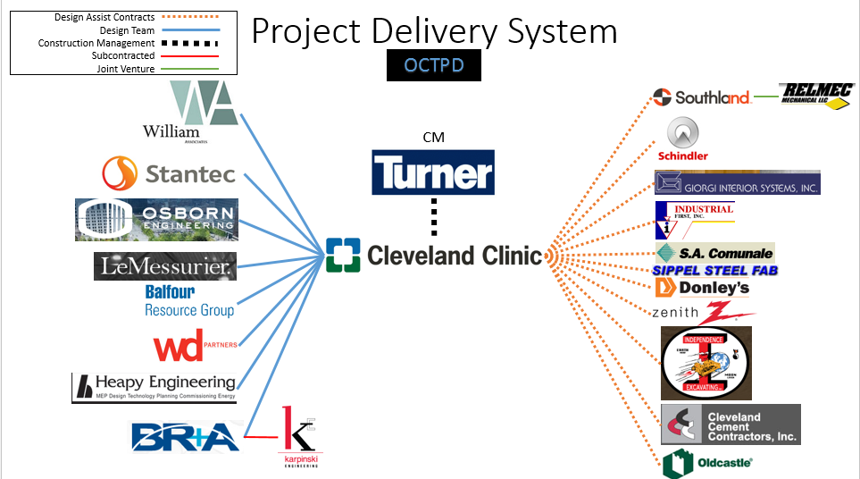
Fig. 10. The general project delivery system of the Cleveland Clinic Cancer Center project.
Electrical
The electrical system has two main feeder for the building that come in at 15kV a piece. These feeders service dual line switchgear at the lower level in the north eastern part of the basement and are directed from the existing Cleveland Clinic Campus substations into an automatic transfer switch. From there the power is distributed through transformers that take the power from 14.4 KV out the building panels at three phase 277/480 volts with 600AMP bus size. This electrical system contains a large amount of redundancy due to the demand of the medical equipment contained within the building. There is an Uninterrupted Power System, UPS, rated at 300kW in order to withstand the electrical loading of the building enough for the backup generators to kick on and start up. These generators are 2000kW and exist in an emergency electrical room on the 7th floor.
Lighting
The Cancer Center contains primarily LED lighting throughout the building. Within the system the only lighting that will not be controlled through relay panels will be the Life Safety lighting. Interesting features of lighting throughout the building include occupancy sensors and dimming sensors that determine the necessity of light output based on the space daylighting. For single or triple lighting fixtures they will be wired together to minimize ballasts but for every fluorescent T8 lamp fixtures they will contain electrical ballasts.
Mechanical
The Cancer Center will serve as both an office space on the upper floors five and six and also medical infusion rooms and cancer treatment center from floors four and below. This is a primary reason the mechanical system is designed with four air handling units that service a variable air volume system. The entire project contains roughly 400 VAV boxes both supply and return air back to the air handlers located in the penthouse. Due to the excessive loads of the medical portion of the building there will be two custom air handling units placed to handle the lower level through the fourth floor. The other two modular units will be used to service the east fifth and sixth floors and west fifth and sixth floors respectively.
Structural
The Framing on the Cancer center is primarily structural steel with braced framing strategically placed throughout to withstand horizontal loading. The Structural steel framing is tied in to the slab with composite shear studs at every major beam. These shear studs tie into the reinforced concrete to also give the entire structure more lateral bracing for wind and other horizontal loading.
The most interesting structural feature of this building is the large cantilevered section of the south facing side of the building. With approximately a third of the building being cantilevered the structural engineers had to create a unique solution to adequately transfer the loads of the building into the foundation. As you can see in the figure this was done by creating very large moment connections at the top of the structure with gusset plate connections. These gusset plate connections are located at the top of the structure where the two red highlighted steel pieces come together to make a point.
Fig. 11. The Structural Components of the Cancer Center and how the first level is indented leaving the remaining 6 floors above cantilevered.
Fire Protection
The building’s fire protection system is a combination standpipe/sprinkler system which will comply with NFPA 101 Life Safety Code. The suppression system is to be a looped system with each floor as a single zone. The different initiation devices include manual pull stations, smoke detectors, and in-duct smoke detectors. The four stage suppression system includes the pre-alert, alarm, tamper, and trouble stages of the fire suppression. If these systems are initiated the remaining systems that may be activated include emergency generators, AHU override switches and power disconnects, fire/smoke damper controls, and smoke exhaust control fans. Based on the initiation device and location within the building one or a sequence of the following will be activated.
Transportation (elevators)
This building contains electric traction elevators. These Gearless Traction Elevators must contain a minimum of 4000lbs for passenger elevators and 5000lbs for the passenger/service swing cabs. The Elevators are to reach a minimum speed of 500FPM. These elevators are equipped with emergency power supply in case of emergency. They are also fire rated at 1.5 hours with a thirty minute temperature rise of 450 degrees.
Telecommunications
Telecommunications include data, voice, patient monitors, and IPTV with different telecommunication outlets located throughout the building. The codes needed to be complied with include EIA/TIA, ANSI, ICEA, BICSI standards as well as applicable National Electric Code Sections and Ohio Building Code. Other than these specific codes, the system is designed to be flexible but available to meet the demands of the building purposes.
Curtain Wall System
The envelope of the entire building is a large wrapped curtain wall of glazed glass with only about 20-30% of the building stone curtain wall system. There are also aluminum louvers located at the top of the building for the intake and exhaust for the air handling units. Because the building is so high in the air the construction process has been modified to make the curtain wall system installation move faster. The system consists of a smaller more portable floor mounted crane/hoist located on the floor above to drag and hold into place the curtainwall system for the floor below. The only issue with this is that the workers would need full access to the floor below which prohibits others from being able to complete work on those floors during that time.
The curtain Wall system is responsible for not permitting condensation due to temperature differences from the outside and inside, must be designed to withstand +/- 27.5 PSF of latter loading from wind. The System must be designed to account for 40PSF ground snow load and 28PSF roof snow load plus drift. The safety factor for the system is 1.5 and the entire system will be installed with the Cleveland climate in mind.